Page 2 of 5

Re: Correcting for a curved film plane?

Posted: 2011-06-06T10:58:04-07:00
by Mark Sirota
Great work and many thanks, everyone who has participated!

I found a much better test photo on Flickr, and have asked permission to use it and post here. I'll let you know.

Re: Correcting for a curved film plane?

Posted: 2011-06-06T13:50:13-07:00
by whugemann
Looks like the fence is perfectly straight now, so we got our mathematics probably correct ;-)

And yes, I forgot that we need the inverse transformation for the mapping.

I think that the cylindrical projection is a standard projection that should be included in the -distort option. It is one of the standard projections in panorama stitching -- however, for other reasons and probably inverse to its application in this very case: The objects caught in the photographs are supposed to fall on a cylindrical plane and were mapped to the image plane of the photograph. They are then back-mapped onto a cylindrical plane, see http://hugin.sourceforge.net/docs/manua ... ction.html

Re: Correcting for a curved film plane?

Posted: 2011-06-06T14:28:05-07:00
by fmw42
Here are the scripts to expand:

Input:
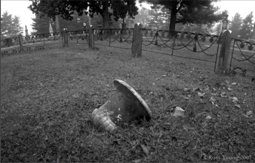
Image


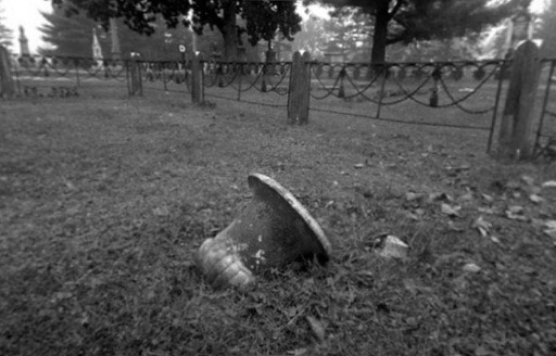
Bilinear Interpolation -- same size as input

infile="P90achop.jpg"
inname=`convert $infile -format "%t" info:`
rr=`convert $infile -ping -format "%[fx:w*57/90]" info:`
w2=`convert $infile -ping -format "%[fx:w/2]" info:`
h2=`convert $infile -ping -format "%[fx:h/2]" info:`
echo "rr=$rr; w2=$w2; h2=$h2"
convert $infile -monitor \
-fx "xx=(i-$w2); aa=atan(xx/$rr); yy=(j-$h2); u.p{$rr*aa+$w2,yy*cos(aa)+$h2}" +monitor \
${inname}_corrected4.jpg
Image


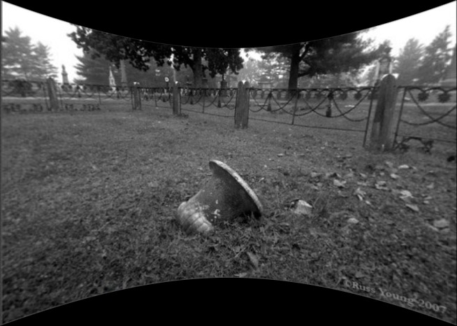
Bilinear interpolation -- wider and taller than input -- shows curved top and bottom

infile="P90achop.jpg"
inname=`convert $infile -format "%t" info:`
rr=`convert $infile -ping -format "%[fx:w*57/90]" info:`
w2=`convert $infile -ping -format "%[fx:w/2]" info:`
h2=`convert $infile -ping -format "%[fx:h/2]" info:`
ww=`convert xc: -format "%[fx:2*$rr*tan(0.5*90/57)]" info:`
hh=`convert xc: -format "%[fx:2*$h2/cos(45/57)]" info:`
ww2=`convert xc: -format "%[fx:$ww/2]" info:`
hh2=`convert xc: -format "%[fx:$hh/2]" info:`
echo "rr=$rr; w2=$w2; h2=$h2 hh=$hh; ww=$ww; ww2=$ww2; hh2=$hh2"
convert -size ${ww}x${hh} xc: $infile -virtual-pixel black -monitor \
-fx "xx=(i-$ww2); aa=atan(xx/$rr); yy=(j-$hh2); v.p{$rr*aa+$w2,yy*cos(aa)+$h2}" +monitor \
${inname}_corrected6.jpg
Image


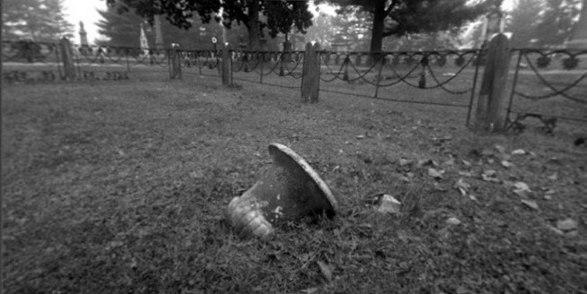
Bilinear interpolation -- wider than input, but properly limited in height so as not to show background fill
infile="P90achop.jpg"
inname=`convert $infile -format "%t" info:`
rr=`convert $infile -ping -format "%[fx:w*57/90]" info:`
w2=`convert $infile -ping -format "%[fx:w/2]" info:`
h2=`convert $infile -ping -format "%[fx:h/2]" info:`
hh=`convert xc: -format "%[fx:2*$h2]" info:`
ww=`convert xc: -format "%[fx:2*$rr*tan(0.5*90/57)]" info:`
ww2=`convert xc: -format "%[fx:$ww/2]" info:`
echo "rr=$rr; w2=$w2; h2=$h2 hh=$hh; ww=$ww"
convert -size ${ww}x${hh} xc: $infile -monitor \
-fx "xx=(i-$ww2); aa=atan(xx/$rr); yy=(j-$h2); v.p{$rr*aa+$w2,yy*cos(aa)+$h2}" +monitor \
${inname}_corrected5.jpg
Image


Bicubic interpolation -- wider than input, but properly limited in height so as not to show background fill. Slightly sharper result

infile="P90achop.jpg"
inname=`convert $infile -format "%t" info:`
rr=`convert $infile -ping -format "%[fx:w*57/90]" info:`
w2=`convert $infile -ping -format "%[fx:w/2]" info:`
h2=`convert $infile -ping -format "%[fx:h/2]" info:`
hh=`convert xc: -format "%[fx:2*$h2]" info:`
ww=`convert xc: -format "%[fx:2*$rr*tan(0.5*90/57)]" info:`
ww2=`convert xc: -format "%[fx:$ww/2]" info:`
echo "rr=$rr; w2=$w2; h2=$h2 hh=$hh; ww=$ww"
convert -size ${ww}x${hh} xc: $infile -interpolate bicubic -monitor \
-fx "xx=(i-$ww2); aa=atan(xx/$rr); yy=(j-$h2); v.p{$rr*aa+$w2,yy*cos(aa)+$h2}" +monitor \
${inname}_corrected5b.jpg
Image

Re: Correcting for a curved film plane?

Posted: 2011-06-06T17:42:43-07:00
by Mark Sirota
Awesome. These don't seem to take into account the half-pixel error mentioned earlier by Anthony, right?

The owner of the photo I mentioned earlier has given his permission for us to use his photo as a test, but unfortunately he hasn't set the permissions at Flickr such that we can download it.

Can anyone come up with a clever way to avoid having to specify the 57x90 dimensions explicitly? It's not reliable, because the film scan won't cover exactly the 57x90 area consistently. For film scan corrections, it would be more natural to specify the radius of the cylinder (the focal length of the camera), would would be multiplied by the image resolution (ppi value in metadata) to determine the radius in pixels.

Alternately, specifying the field of view (another camera-specific value) would be enough. We know the horizontal dimension in pixels. In this case we can calculate the circumference by multiplying the horizontal dimension by four, then divide by 2*pi to get the radius.

Re: Correcting for a curved film plane?

Posted: 2011-06-06T18:24:20-07:00
by anthony
The fact that straight lines are coming out as straight lines is a good indication that the distortion is correct.

A pinhole camera will have not lens distortions so you should see no pin-cushion or barrel distortions. Straight lines should be straight lines. As such I think you have it.

So for a +distort that tries to recover all the converted data is...

Code: Select all

infile="P90achop.jpg"
inname=`convert $infile -format "%t" info:`
rr=`convert $infile -ping -format "%[fx:w*57/90]" info:`
w2=`convert $infile -ping -format "%[fx:w/2]" info:`
h2=`convert $infile -ping -format "%[fx:h/2]" info:`
ww=`convert xc: -format "%[fx:2*$rr*tan(0.5*90/57)]" info:`
hh=`convert xc: -format "%[fx:2*$h2/cos(45/57)]" info:`
ww2=`convert xc: -format "%[fx:$ww/2]" info:`
hh2=`convert xc: -format "%[fx:$hh/2]" info:`
echo "rr=$rr; w2=$w2; h2=$h2 hh=$hh; ww=$ww; ww2=$ww2; hh2=$hh2"
convert -size ${ww}x${hh} xc: $infile -virtual-pixel black -monitor \
-fx "xx=(i-$ww2); aa=atan(xx/$rr); yy=(j-$hh2); v.p{$rr*aa+$w2,yy*cos(aa)+$h2}" +monitor \
${inname}_corrected6.jpg
What is '57' ?

coefficients needed for the FX appears to be just... $rr which is a angle scaling factor

with $w $h as the input image size
and $w2 and $h2 being the center of the distort in source image in input (center of image)
corresponding to $ww $hh the output viewport size
with $ww2 and $hh2 being the center of the distortion in output viewport. (center of viewport by default)


As such the only thing that appears to be needed as arguments for the distortion (other than input image)
seems to be what type of 'viewport' is wanted (original image size, expanded width, or unclipped)
the first and last is straight-forward, -distort and +distort. and the middle can be cropped form the result
after the fact.

As such there is no input arguments for this distort, except posibly the 'x' in the input image you want to be the center (least distorted) point of the input image.


What about the reverse? flat to cylindrical?

Re: Correcting for a curved film plane?

Posted: 2011-06-06T18:28:13-07:00
by fmw42
the 90/57 (=1.57894736842) is the exact fov in radians and comes out close to 90 degrees (pi/2=1.57079635 radians). I used that because the actual fov was not provided, except to say it was nearly 90 degrees. The 90 in the above is the film width in mm and the 57 is the focal length in mm. My script below is modified so that if you know the fov as follows (just skip the wmm and rmm) and provide a variable value directly for fov.


infile="P90achop_sm.jpg"
inname=`convert $infile -format "%t" info:`
wmm=90
rmm=57
fov=`convert xc: -format "%[fx:$wmm/$rmm]" info:`
rr=`convert $infile -ping -format "%[fx:w/$fov]" info:`
w2=`convert $infile -ping -format "%[fx:w/2]" info:`
h2=`convert $infile -ping -format "%[fx:h/2]" info:`
ww=`convert xc: -format "%[fx:2*$rr*tan(0.5*$fov)]" info:`
hh=`convert xc: -format "%[fx:2*$h2/cos($fov/2)]" info:`
ww2=`convert xc: -format "%[fx:$ww/2]" info:`
hh2=`convert xc: -format "%[fx:$hh/2]" info:`
echo "rr=$rr; w2=$w2; h2=$h2 hh=$hh; ww=$ww; ww2=$ww2; hh2=$hh2"
convert -size ${ww}x${hh} xc: $infile -virtual-pixel black -monitor \
-fx "xx=(i-$ww2); aa=atan(xx/$rr); yy=(j-$hh2); v.p{$rr*aa+$w2,yy*cos(aa)+$h2}" +monitor \
${inname}_corrected6c.jpg

Anthony will have to answer about the half pixel issue, but I used w/2 and h/2 as the middle of the image rather than (w-1)/2 and (h-1)/2. So that should be consistent with the correction for the half pixel issue of image vs pixel coords. I don't know if that is totally sufficient, however, and Anthony will need to answer that.

One other possible change with respect to the half pixel issue, I think might need

rr=`convert $infile -ping -format "%[fx:w/$fov]" info:`

to become

rr=`convert $infile -ping -format "%[fx:(w+1)/$fov]" info:`

Re: Correcting for a curved film plane?

Posted: 2011-06-06T18:31:03-07:00
by fmw42
anthony wrote:The fact that straight lines are coming out as straight lines is a good indication that the distortion is correct.

Correct, but you note that the top and bottom of the corrected image are not straight lines but curved. So the vertical distortion is not linear with width.

Re: Correcting for a curved film plane?

Posted: 2011-06-06T19:38:27-07:00
by anthony
The correction for pixel to image coodinates (the 1/2 pixel) is simple

Add 0.5 to xx,yy then subtract 0.5 during the actual v.p{...} lookup.
Transforming it to the same style I use for -verbose distort output of an FX equivalent (as a distort math check)
http://www.imagemagick.org/Usage/distor ... rt_verbose

Code: Select all

-fx "xx=(i-$ww2+0.5); jj=(j-$hh2+0.5);
       aa=atan(ii/$rr); 
       xx=$rr*aa+$w2; yy=jj*cos(aa);
       v.p{xx+$w2-0.5,yy+$h2-0.5}"
Of course I would typically also include some page virtual offsets as well :-)

So 90 is not an angle but a film height, and 57 is focal length (or radius), with film arranged
to place pin hole in the center of a 90 degree arc of film.

I suppose that makes sense.

But these should be able to be calculated from the size of the image itself. That is we know the width of the image is to form a arc of 90 degrees (optional argument), and the pinhole (focal length) is exactly in the center of that arc. Also we have the aspect ratio for the height. so radius=forcal_length=width*2/PI (for a 90 degree arc).

Fred can you give me that calculation?

That way we can handle odd sized 'films' too, or ones that have been cropped, or non-photographer.
I hope I can be allow to use the diagrams previously provided in my examples?


What should the distort be called? Does this type of photo have a specific name?

EG: -distort ??? "90,center_x,center_y"
where 90 is the arc of the film in degrees, and center is optional center of distortion (optional)

PS: it is posible to get an infinite image with a x-center set to an edge of a 90 degree arc, so a limit of 45 degree from that center in output may be wise (unless a user viewport is specified).

Re: Correcting for a curved film plane?

Posted: 2011-06-06T19:51:52-07:00
by fmw42
But these should be able to be calculated from the size of the image itself. That is we know the width of the image is to form a arc of 90 degrees (optional argument), and the pinhole (focal length) is exactly in the center of that arc. Also we have the aspect ratio for the height. so radius=forcal_length=width*2/PI (for a 90 degree arc).

Fred can you give me that calculation?
The issue is that the fov is not exactly 90 degrees. That is why I had to calculate it from the width of the image in mm and the focal length in mm. Recall that the input image is on a cylinder but unwrapped to be flat. The focal length is the radius of the cylinder. And the arc length formula for the extent of the cylinder is given by s=r*fov where s=width of input image. Thus fov=w/r=90mm/57mm.

What should the distort be called? Does this type of photo have a specific name?

EG: -distort ??? "90,center_x,center_y"
where 90 is the arc of the film in degrees, and center is optional center of distortion (optional)
I was going to script this eventually and would have called it cylinder2rect as it corrects a cylinder distortion to a rectangular form or cylinder2perspective as the rectangular form is a perspective image (i.e. pinhole camera onto a plane). The key argument is the fov. But in the above, I had to compute it from the focal length and image dimension both in physical rather than pixel dimensions.

As a distort, I am not sure what I would call it other than something like the above or something like decylinderize. I will think about other names.

If I only had one or two MagicFilter kit templates that would allow me to put formula like fx into them (i.e. do one or two input image reverse transformations, I could program some -process functions to do many of these.
PS: it is posible to get an infinite image with a x-center set to an edge of a 90 degree arc, so a limit of 45 degree from that center in output may be wise (unless a user viewport is specified).
A fov=180 would certainly be a problem, but I don't think you need to limit it to fov=90. I believe that one can still do larger fov values before it goes to wild. I would guess even 120 degrees would not be too bad. Recall the height of the output varies as 2/cos(fov/2). So

fov=90 would only be 1.4 times as tall as the input
and
fov=120 would be 2 times as tall as the input
and
fov=160 would be 3.8637 times as tall as the input

So it really only starts going wild rapidly when you get close to fov=180.

Re: Correcting for a curved film plane?

Posted: 2011-06-06T20:10:32-07:00
by anthony
that makes it harder for handling other cylindrical images such as the 360 degree one on the Hugin page
http://hugin.sourceforge.net/docs/manua ... ction.html

It may be that the FOV (in degrees) will need to be the one non-optional argument to a clindrical2plane projection.

The P.90 camera would in that case have a arc angle of 90/57*180/PI or 90.467 degrees. That is pretty close to 90!

I would not be surprised it may be that it is actually engineered to be 90 degrees, but with 57mm being a near approximation (for advertising). We would need to know for certain!

Re: Correcting for a curved film plane?

Posted: 2011-06-06T20:16:14-07:00
by fmw42
that makes it harder for handling other cylindrical images such as the 360 degree one on the Hugin page
http://hugin.sourceforge.net/docs/manua ... ction.html
I believe after looking at that the page that it is not describing the same kind of transformation. It is describing a sphere projected onto an cylinder which is then unwrapped. (A mercator-like mapping transformation). We are doing a partial cylinder projection onto a perspective plane.

Re: Correcting for a curved film plane?

Posted: 2011-06-06T20:31:51-07:00
by fmw42
I would not be surprised it may be that it is actually engineered to be 90 degrees, but with 57mm being a near approximation (for advertising). We would need to know for certain!
Actually the specs on the reference page say it is nearly 90 degree field of view and give a specific focal length of 57. So one has to believe what they say and not infer too much. The f stop is well defined and so is the focal length which is related to it. So I would tend to believe that rather than assuming that the fov is truly 90 degrees.

Re: Correcting for a curved film plane?

Posted: 2011-06-06T20:41:03-07:00
by anthony
fmw42 wrote:
that makes it harder for handling other cylindrical images such as the 360 degree one on the Hugin page
http://hugin.sourceforge.net/docs/manua ... ction.html
I believe after looking at that the page that it is not describing the same kind of transformation. It is describing a sphere projected onto an cylinder which is then unwrapped. (A mercator-like mapping transformation). We are doing a partial cylinder projection onto a perspective plane.
No the image on that page is not a sphere in a mercator-like (world map) projection. If it was the top and bottom of the image will all be a single color.
It is definably a cylinder projection.

Of course any cylinder (or sphere) to plane distortion mapping would produce an infinite 'flat' image when angle from center of distortion reaches 90 degrees, as at that point the view becomes parellel to the flat plane! (limit of the tan() function). As such using the hugin cylinder image, you would only be able to convert a small part of the image. It could however be used to generate a set of four 'cube face' images :-)

I would probably include some angle limit to the output of any cylinder/sphere to rectangular. Anything more than 60 degree from center is probably getting ridiculous. Such a limit is not needed for the reverse, as you could never input an infinite plane image.

So we may need to include arc limits as some of the optional arguments that need to be worked out! (unless the user inputs a 'viewport' image that will bypass the need for limits). And I need to know before I start implementing as it is harder to add them later!
Actually the specs on the reference page say it is nearly 90 degree field of view and give a specific focal length of 57. So one has to believe what they say and not infer too much. The f stop is well defined and so is the focal length which is related to it. So I would tend to believe that rather than assuming that the fov is truly 90 degrees.
Fair enough. But it will still probably be provided as required user input argument of 90.467

Re: Correcting for a curved film plane?

Posted: 2011-06-06T20:47:11-07:00
by fmw42
From http://hugin.sourceforge.net/docs/manua ... ction.html it says:

A cylindrical projection is a type of projection for mapping a portion of the surface of a sphere to a flat image. It can be envisioned by imagining wrapping a flat piece of paper around the circumference of a sphere, such that it is tangent to the sphere at its equator. Shining a light from the center of the sphere then projects the spherical surface onto the flat paper.

and references http://mathworld.wolfram.com/CylindricalProjection.html at the bottom where it says

"Cylindrical projection at Mathworld[*] shows an example and gives details on the mathematics"

click the asterisk to see the diagram of the projection

Re: Correcting for a curved film plane?

Posted: 2011-06-06T21:04:23-07:00
by fmw42
anthony wrote:
Of course any cylinder (or sphere) to plane distortion mapping would produce an infinite 'flat' image when angle from center of distortion reaches 90 degrees, as at that point the view becomes parellel to the flat plane! (limit of the tan() function). As such using the hugin cylinder image, you would only be able to convert a small part of the image. It could however be used to generate a set of four 'cube face' images :-)

I would probably include some angle limit to the output of any cylinder/sphere to rectangular. Anything more than 60 degree from center is probably getting ridiculous. Such a limit is not needed for the reverse, as you could never input an infinite plane image.

So we may need to include arc limits as some of the optional arguments that need to be worked out! (unless the user inputs a 'viewport' image that will bypass the need for limits). And I need to know before I start implementing as it is harder to add them later!
Sorry, I thought you were worried about the height which as I described above varies as 2/cos(fov/2).

fov=90 would only be 1.4 times as tall as the input
fov=120 would be 2 times as tall as the input
fov=160 would be 3.8637 times as tall as the input

But the width varies as tan(fov/2)/(fov). So for

fov=90 we get the output width as 1.27324 times input width
fov=120 we get the output width as 1.65399 times input width
fov=160 we get the utput width as 4.06176 times input width