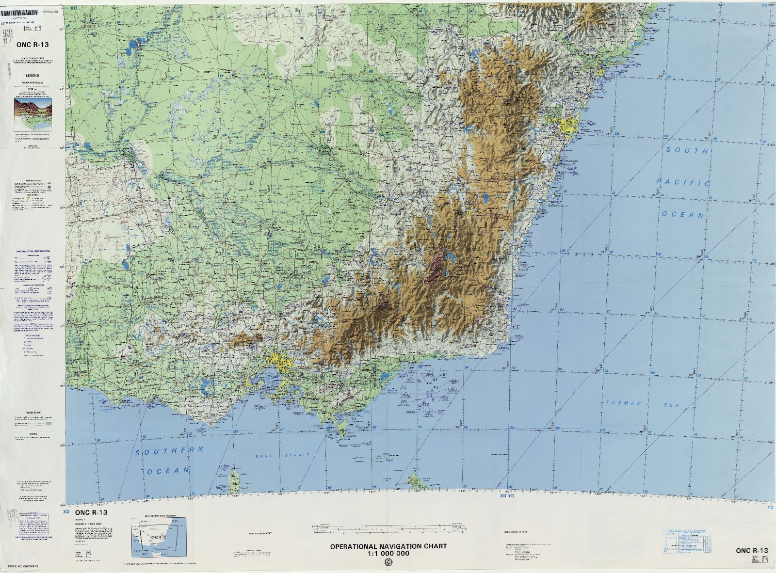
This may be tricky. De-polar was designed specifically to reverse a polar distorted image.
You know where the center is, but you will need to specify the angles and radius in which your map lies relative to that center.
The angles, and radius is what is then maped into the sides and top/bottom edges of the final image.
Okay image is 1600x1182 pixels. the center is at 4412,96810
So mapping the four corners into an angle
Code: Select all
 corner    --> relative to center  -> radius      angle
  0,0                -4412,-96810        96910
 1600,1182      -2812,-95628         95668
0,1182             -4412,-95628                       -177.36
1600,0             -2812,-96810                       -178.33
convert input_map.jpg +distort Depolar '96910 95668 4412,96810 -178.33 -177.36' +repage show:
Which is again very long and thin. Expanding the angles to -200 to -100 produces a more square output, but it is blank.
Adding verbose should let use see the reverse mapping, whcih should be mapping destination image pixels into angle,radius, and mapping that to source image lookups.
Code: Select all
convert input_map.jpg -verbose +distort Depolar '96910 95668 4412,96810 -200 -100' +repage show:
DePolar Distort, Internal Coefficents
  c0 = +96910.000000
  c1 = +95668.000000
  c2 = +4412.000000
  c3 = +96810.000000
  c4 = -3.490659
  c5 = -1.745329
  c6 = +0.001610
  c7 = +1.000000
DePolar Distort, FX Equivelent:
  -size 1084x1242 -page +0+0 xc: +insert \
  -fx 'aa=(i+.5)*0.001610 +3.490659;
       rr=(j+.5)*1.000000 +95668.000000;
       xx=rr*sin(aa) +4412.000000;
       yy=rr*cos(aa) +96810.000000;
       v.p{xx-.5,yy-.5}' \
FYI the 'c' values are the coefficents the user input arguments are converted into
c0,c1 radius for Y coodinate C0 only used for determining +distort image bounds
c2,c3 center of polar plot (in mathematical coodinates perhaps it you need +0.5 for center of a pixel?
c4,c5 given angles in radians
c6,c7 increment and scaling for pixel coordinates to angle,radius respectively.
I am not certain what is wrong with the scaling of angle to (X in destination image), whcih is the c6 coefficent.
The white (border edges of the original image) seems to indicate that the above calculation is missing the original image (only producing virtual pixels). Adding -virtual-pixel tile shows it is doing something but it is not what is expected (actually the result is a rather lovely 'wood grain' type pattern!!!!
Code: Select all
convert input_map.jpg -virtual-pixel tile +distort Depolar '96910 95668 4412,96810 -200 -100' +repage show:
As such I think I have the angles wrong... Looking in quadrants... okay found the map in the third quadrant -- whcih is close
but not exactly where I thought the image should have been! (my angle calculation was off)
Code: Select all
convert input_map.jpg -virtual-pixel gray +distort Depolar '96910 95668 4412,96810 -180 -170' +repage -scale 80% show:
verbose...
Code: Select all
DePolar Distort, Internal Coefficents
  c0 = +96910.000000
  c1 = +95668.000000
  c2 = +4412.000000
  c3 = +96810.000000
  c4 = -3.141593
  c5 = -2.967060
  c6 = +0.001601
  c7 = +1.000000
DePolar Distort, FX Equivelent:
  -size 109x1242 -page +0+0 xc: +insert \
  -fx 'aa=(i+.5)*0.001601 +3.141593;
       rr=(j+.5)*1.000000 +95668.000000;
       xx=rr*sin(aa) +4412.000000;
       yy=rr*cos(aa) +96810.000000;
       v.p{xx-.5,yy-.5}' \
The FX equivelent version generates the same image!
Code: Select all
convert input_map.jpg -virtual-pixel gray \
  -size 109x1242 -page +0+0 xc: +insert \
   -fx 'aa=(i+.5)*0.001601 +3.141593;
      rr=(j+.5)*1.000000 +95668.000000;
      xx=rr*sin(aa) +4412.000000;
      yy=rr*cos(aa) +96810.000000;
      v.p{xx-.5,yy-.5}' \
   show:
But the calculated viewport image is very badly distorted. That seems to indicate something about converting the angle range for that radius is going badly wrong. Probably it using angle* half maximum radius, rather than angle*(max-min_radius)/2
The height (radius difference) is right, just width (angle) calculation, (angle per X pixel step))
I really can not see what is wrong..
c6 calculation is...
Code: Select all
coeff[6]=(coeff[5]-coeff[4])/geometry.width
where geometry.width is the calculated width for the output image.
that width is...
geometry.width = (size_t)
ceil((coeff[0]-coeff[1])*(coeff[5]-coeff[4])*0.5);
or radius_average * angle_difference
or (96910-95668)/2 * ((-2.967060)-(-3.141593)) => 108.3 => 109 pixels.
Everything seem right, So I really can't see why it is wrong.

