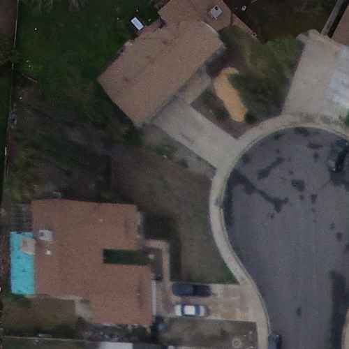
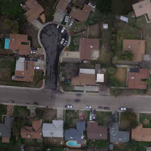
We can consider this as a general blending problem. A number of my pages (not all published yet) are about blending, though on a smaller scale, up to a dozen images. The same principles apply to thousands.
There are two major issues: geometry and photometry.
Geometry: The two shapes on these images can't be made to match with a simple translation. They also need a rotation and perspective transformation, perhaps due to tilt of the aircraft. To see this, try:
Code: Select all
%IM%convert ^
  aerial01.jpg ^
  ( aerial08.jpg ^
    -repage +2100+1000 ^
    -alpha set ^
    -channel A -evaluate set 50%% +channel ^
  ) ^
  +write info: ^
  -layers merge ^
  overlap18.png
(All code is Windows BAT syntax. Adjust as required for your shell.)
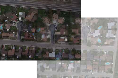
Provided the same camera and lens is used for all photos, and the lens is close to rectilinear, my page "Simple alignment by matching areas", using Perspective Distortion, should solve the geometry problem.
Once overlaps have been determined, one image can be made to match another photometrically (brightness, contrast and colour cast). In this example pair, we can extract the two overlaps, approximately:
Code: Select all
%IM%convert ^
  aerial01.jpg ^
  -crop 1000x1000+2100+1000 +repage ^
  over1.png

%IM%convert ^
  aerial08.jpg ^
  -crop 1000x1000+0+0 +repage ^
  over8.png
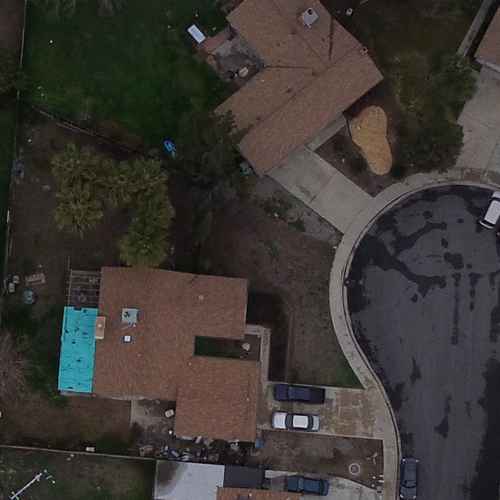
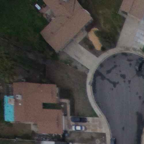
One simple photometric adjustment is gain and bias, which adjusts the brightness and contrast of each channel independently. One image can be made to match another, or both adjusted to a common standard. From my "Gain and bias" page:
Code: Select all
call %PICTBAT%imgGainBias ^
  over1.png ^
  over8.png ^
  over1match8.png
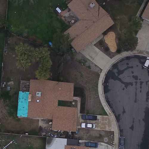
The overlaps match photometrically, more or less. The same transformation can be applied to an entire image.
Instead of gain/bias, we can match histograms:
Code: Select all
call %PICTBAT%matchHisto ^
  over1.png ^
  over8.png ^
  over1matchhist8.png
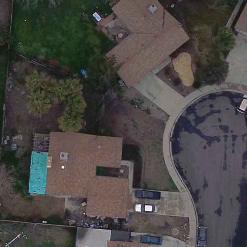
This gives a slightly different result. It is more accurate, provided the overlaps match geometrically. But when used on two images that merely
contain an overlap, it will give spurious results, so the gain/bias method is better.
So, we have solutions for matching the geometry and photometry of images. Then it is a hard slog of processing the thousands of images, working either to a common standard or a sliding standard, and blending the results. This is a good solution for preparing accurate maps.
For flight simulators, I think there is a better solution. In the words of one researcher, "Don't blend it, cut it!".
Instead of matching geometry and photometry then blending one image with another, we simply cut a ragged edge around one image so that when that cut image is placed over the other, the join is not obvious. Then we add another image, and another, reaching thousands. The ragged cut is made where the images match best, a "dark path" within the difference of the images.
This "cutting" method removes the complexity of standards (whether common or sliding), precise geometric alignment, mismatching colour gamuts, and ghosting caused by blending. The virtual landscape below the aircraft will look realistic. True, it won't be as
accurate as the technical mapping method, but it will
appear realistic, and it is far simpler to make.
I haven't published the general technique for doing this with a large number of photos. The simple case of two images is on "Rectangle boundaries with dark paths", and some extensions are shown on other pages.
Code: Select all
call %PICTBAT%rectDp ^
  over1.png ^
  over8.png ^
  over1cut8.png ^
  30c 30c 0 0
